Saturday, April 21, 2012

Temp controlled Fermentation Chamber

Even though our weather is very mild here in San Diego compared to other parts of the nation, our winters can get a little chilly and summers a bit warm.  Especially when you're trying to ferment in the garage where there is very little temp control to begin with. 
I have been sticking my carboys in an old fridge that I have. Which does help.....but it still isn't exactly controlled.
The fix??  A digital temp controller that can be found on Ebay for a little over $20 shipped!

The controller comes with a temperature sensor and has relays for both heating and cooling. Can hold a temp within .3 degrees Celcius (the only downside is that the controller only displays Celcius) and even has a compressor delay so your fridge isn't cycling off and on.

On to the install!

So here is the fridge before:
First I started by pulling the original thermostat apart to see what was inside:
So here you can see the original thermostat on the left with the red and orange wires running to it.  I will basically take these two wires and extend them into my new thermostat (the temp controller) and land them on the cooling side.
The controller also requires 110v to power itself on.  All I did was splice into the wires that feed the lights for the fridge and extend those over to the controller

Another view of the old thermostat:
My next step was cutting the hole for the unit in the door.  Remember to check inside the door too to make sure that you're not in the middle of a shelf or something else that might be in the way of the unit. I used a dremel with a metal cutting wheel to make the cut.
The back side was a little bit more rough.....but thankfully you don't see that side to often

Now with all the wires out of the thermostat enclosure ( I found a nice little hole back by the light bulbs to come out of) I was able to put all the pieces back together so it looked pretty clean

The controller itself was really easy to wire up.  The white and black (my power spliced off of the lights power) fed power to the unit.  The two greens went to the cooling side relay (In this picture the red wire are my cooling wires.  I had used solid core wire to start with because I had it but it was way to rigid in this application.  Especially with the opening and closing of the door.  I used stranded 14 ga. wire instead which worked much better!)


Here it is slid into place

....and from the inside. The loose wire on the shelf is the temperature sensor
Another view of the inside.  

All lit up!


My next step will be to add some kind of heater to the inside and just wire it up the heating side of the controller.  I will probably go with some kind of ceramic aquarium heater.....and a heating pad.

Really happy with how this turned out.  Programming it for the temperatures and compressor delay was fairly simple......the instructions that come with the unit are not the best though.

Now just need to brew some more beer to test this out!!

Saturday, February 11, 2012

Dunkelweiss

Today was a great day.........made even better since the brew kettles were fired up!!
My buddy Kevin wanted to brew a Dunkelweizen.  Having never brewed one I looked it up on BJCP style guideline website and made one up (It's under the German Wheat beer category).
Here is what I came up with for a 10 gallon batch:

10 # Wheat Malt
10# Munich Malt
3/4# Special B
3/4# Carafa II
Since the wheat content is high you're going to want to add about a pound of rice hulls (wheat malt has no husk on the grain.  This becomes a problem when you're draining out your mash tun and the husks aren't there to help filter....which could possibly lead to a stuck sparge.  Rice hulls are cheap insurance)

1 oz. Hallertauer @ 60 minutes
1 oz. Hallertauer @ 30 minutes

I chose to finish it off with White Labs WLP300 Hefeweizen Ale yeast.  I like the banana and clove that comes from this strain

Lets get started!

First gotta get it all set up:

Adding water.....I use a whole house filter now to supply all my brewing water


Flame is on.....and heating up the mash water (Notice the baby monitor next to the mash tun.  I can multi task!!)


Getting close to add the grains in......


Grains are in!  Now we let this sit for about an hour and try to keep our temperature steady around 152F


Ok.....hour is up and we're draining!  Looking good so far.....

 Filling up the brew kettle nicely and the color is looking great!

 Here's whats left of the spent grain

Boil is going and the first hop additions are in:

I think it's time to relax and have a homebrew!  Here's my IIPA I made a few weeks back

Alright....beer is gone....time to set up the chiller.  I am able to chill my wort down to yeast pitching temps in no time with my counterflow chiller.


 Filling up the carboy

Here's her home for the next week or so......Don't worry she will have company.  That is only half the batch right there.

So at 70% efficiency I was right on all day long.
I collected about 11 gallons of wort and my Original gravity was 1.053. Now it's time for the yeast to get to work!


Friday, January 27, 2012

My mash paddle

Finally got around to making a mash paddle.  I got tired of trying to stir the mash with my long (but not long enough) plastic spoon that comes with most homebrewing starter kits.

I went to a local lumber distributor and asked their opinion on a good hard wood to use that would be food safe.  He suggested cherry, ash, maple....I went with cherry.  I picked up an 1x4 8 footer so I still have some left over to make another one later

To start off I drew out my paddle.   Total length is 36" with the paddle section being 18".  I left the paddle width the complete 4".

You can faintly see my pencil markings on the board.  I drew my handle out to 1 1/2" and after everything was cut out I am happy with the width.  I just used a jigsaw and went real slow to cut out the shape and a hole saw to drill the holes.  I suppose you could leave it blank, with no holes, but I like the holes to help break up the grain dough balls when you're mashing in.

I just kinda randomly places holes. The bigger ones are 2" with the smaller ones being 1"
After being cut and drilled out I just sanded it down.  I've read that the wood can either be left alone or treated with butchers block oil.  I think for now I'm just going to leave it alone and see how it holds up.  I still need to get a new drum sander for my Dremel to finish out the insides of the holes.  Other than that I'm very happy with how it turned out.

Just need to break it in now!


Wednesday, January 25, 2012

DIY Stir Plate

This entry goes along with the last one. 
One of the best ways to ensure that you have a healthy yeast starter is to use a Stir Plate.  Basically a stir plate is a spinning magnet (mounted on a motor) that in turns spins a magnetic "stir bar" in a flask with your wort and yeast mixture that you prepared from the previous blog entry.
Stir Plates can be found online or at local homebrew shops for $40 on up.  I love tinkering around in the garage.....so of course I built my own!

First you need an enclosure or box of some sort. I had an old cigar box laying around that worked out perfectly.  Radio shack also sells project boxes for around $5 that would work as well.

Next you need some kind of motor and magnet to spin your stir bar.  Also needed is power supply.  Definitely not needed.....but a nice addition is some kind of speed control to control the speed of the magnet spinning in your wort.  Most of us have an old computer laying around that has most of the necessary parts.  I used a fan out of an computer along with a magnet that I robbed off of the hard drive from the same computer.  Just an FYI.......Only take these parts out of a computer that you definitely have no desire to ever use again!  My power supply came from an old power supply for an old modem that I had.  I played around with some old cell phone chargers and none seemed to have the power needed to spin the magnet like I wanted.  Most power supplies lists what the output is.  The one I picked was 12V and 1 amp.  I used a hot glue gun and glued my hard drive magnet to the center of the fan.

Next I mounted the fan to bottom side of the lid of my cigar box.....and then wired up the power supply.  I also added a switch for ease of use.

Here's the front of my box with the switch and the speed control.  I need to pick up a different knob for my speed control.


Here she is spinning a vase of water.  Pulling a nice vortex!

Remember.....oxygen is needed for good yeast cell reproduction......I usually use a piece of foil or saran wrap to cover the top of my flask.  Need to keep the bad out.....but let the oxygen in. Here's a good example:


Please feel free to ask any questions you may have!

Yeast Starter

After all the boiling, adding hops, and cooling to fermentation temperatures comes the yeast.  Yeast is a living organism that eats up all the available sugar....bi-product being alcohol and CO2.  A good yeast starter supplies plenty of healthy yeast ready to go to work on your brew. Starters usually results in less lag time from time of pitching yeast to start of fermentation.

Here's the link  Homebrewing wiki on making a starter.  

http://www.homebrewtalk.com/wiki/index.php/Yeast_Starters


Yeast Starters


With most liquid yeasts, the use of a starter is necessary in order to create a viable amount of pitchable yeast. Even yeasts marketed as directly pitchable can benefit from the creation of a starter. A starter reduces lag time, before fermentation commences, and can help prevent a stuck fermentation. A typical starter involves fermenting a vial or package of liquid yeast in a small amount of wort a few days before brewing. Dry yeasts typically do not require a starter. Making a starter with dry yeast can be detrimental to their performance because they may deplete their nutrient reserves before pitching.

Contents

[hide]

[edit] Theory

The recommended pitching rate for most ales is 0.75M-1M cells/(mL*P) and 1.5M-2M cells/(mL*P) for most lagers, where P is the degrees Plato of the wort. Given unlimited oxygen and nutrient supplies (think DAP and Stir Plate), a starter produces 10M-15M cells/(mL*P). Most brewers restrict the Plato of the starter to be 10P or less, citing yeast stress and off-flavors for more concentrated starters.
For example, suppose I want to make a starter for 19L of ale at 12P. This requires 1M cells/(mL*P) * 19,000mL * 12P = 228G cells (228 billion). Since the typical White Labs vial and Wyeast Activator packet only provide 100G cells, it is in my best interest to make a starter. If the starter wort is 10P, then the volume of the starter should be 228G cells / (10M cells/(mL*P) * 10P ) = 2,228 mL.

[edit] Yeast Starter Procedure

Making a starter is relatively straightforward, far easier than brewing an entire batch of beer.
  • Allow yeast to come to room temperature. If it is a smack pack, smack it first.
  • Bring one pint of water to a boil in a two quart saucepan on the stove top.
  • Reduce the heat, add one half cup of Dry Malt Extract (DME) to the water, and mix it thoroughly.
  • Gently boil the wort for ten minutes.
  • Remove the saucepan from the stove top, and cool it to room temperature, ~75ºF (~24ºC).
  • Put the cool wort into an approximately half gallon (~2L) container.
  • Cover and aerate thoroughly.
  • Pour the contents of the yeast vial or smack pack into the container.
  • Shake to mix the yeast into the wort.
  • Cover the container with a piece of foil or a loose-fitting cap. Place on stir plate at this time if you have one.
  • There will be very little sign of activity, but the starter should be ready in one to three days.
  • You may step up the starter by adding additional wort over a period of days.
  • After you have brewed your full batch, you may either:
    • Shake the entire mixture again and pitch it into the wort
OR
  • Chill the mixture a few hours to a day before pitching to drop the yeast out of suspension
  • Decant off the top layer of liquid before pitching just the yeast into the wort

[edit]

Monday, January 23, 2012

Hop Spider!

This little contraption really helps keep most of the hop mess out of the fermentor.  Very simple, yet very effective.


I used a bell end off of a piece of 6" pipe that I had left over from a job, but any 6-8" diameter piece of pipe or coupling will do the trick.  I used 1/4" x 6" bolts with a nut on the inside and outside of pipe to keep it all tight.  I drilled my holes equal distance apart.  My hop bag is a nylon bag with a drawstring that can be found at your local homebrew shop.

I like the lip on this pipe to help hold the hop bag up when the drawstring is pulled tight.  I still tie the drawstring off to one of the bolts just in case
Here's how it sits on top of my keggle


Sunday, January 22, 2012

Counterflow Chiller

One of the best additions to my brewing equipment by far!!
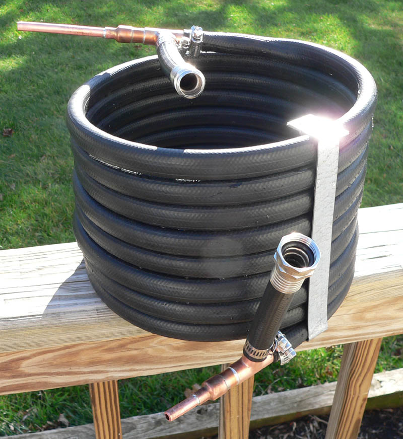
In the past I would buy around 40lbs of ice  every brew day to make an ice bath for my brew kettle to try and cool down the boiled wort. This process would usually take atleast an hour. Now I can chill my wort down to yeast pitching temperatures as fast as I can drain my boil kettle. Basically you have an inner tube (the 3/8 copper) surrounded by a rubber garden hose.  The copper tubing carries the hot wort.  The garden hose carries water straight from your hose bib coming out of your house.  With the hot wort entering the chiller from the top and the cool tap water entering from the bottom the wort will always be in contact with cool tap water
Here's the guide that I used to construct mine:

This is the cheapest way to put a CFC together and doesn't use any pricy compression fittings. It requires soldering, but you ought to know how to do that already. No? Shame. Here's what we're building:
Image:Bobby_M_cfc.jpg
Part list:
  • (1) 12" x 1/2" copper pipe
  • (2) 1/2" copper TEEs
  • (2) 1/2" x 1/4" copper reducers
  • (1) 25' x 3/8" OD soft copper tubing
  • (1) 25' x 5/8" ID rubber garden hose (make sure it's rubber. It will be the only one that does NOT say "do not use with hot water".)
  • (4) hose clamps.

Image:Bobby_M_cfc3.jpg
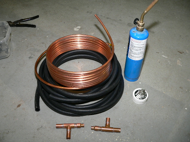
You'll also need some emery cloth (sandpaper), a round wire brush, flux, solder, tubing cutter, and a propane torch.
The first step is to create the end assemblies: Completely clean the 1/2" copper pipe by sanding it with emery cloth, then cut it into six 2-inch pieces with the tubing cutter. Clean the insides of the Tees and reducers with the round wire brush. Apply a liberal amount of flux paste and assemble to look like this:
Image:Bobby_M_cfc1.jpg

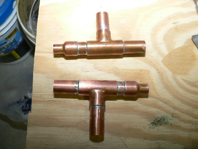
Apply the propane flame and keep it moving but focus mostly on the Tee. Keep testing the temp by removing the flame and touching solder to the joint. If it doesn't flow, apply a little more heat. Don't overheat. You should see the solder being sucked into the joint. A solder joint does not seal due to an apparent bead on the outside of the fitting so don't build it up too much. Once it starts dripping out and falling on the floor, you have more than enough in the joint.
Before moving on, you must drill out the stops inside the reducer fittings with a 3/8" drill bit. There's a nub sticking out inside there that is meant to stop the 3/8 tubing from going all the way through the reducer. This is precisely what we WANT to happen.
The next thing you do is cut the last 10" off of each end of the garden hose. Unroll the soft copper tubing carefully into a straight line. Make up a very soapy solution of dish soap and water and pour it into the hose with a funnel. You can also lubricate with something like KY as long as it's water soluble. Don't try working the copper inside the hose without a lube, you'll only get it about 1/3rd of the way before you start cursing. You'll want to center the hose on the copper so that about 10" of copper sticks out on each end.
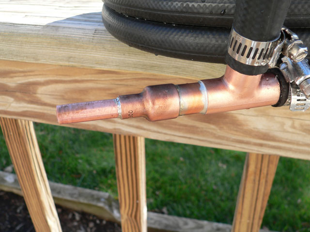
On one end, clean the lubricant off the copper and use the emery cloth to thoroughly clean the copper in prep for soldering. Apply flux to the copper and inside of the reducer on one of the end assemblies and slide it on. For this soldering job, you can slide the rubber hose out of the way, but take note of where the assembly has to sit first. Once you solder the reducer to the inner tubing, you can slide the rubber hose over the end assembly and clamp the hose on tightly.
You not have to select a cylindrical object to coil the hose around and I'd suggest going at least 12" in diameter. Start coiling from the end that you've just soldered. Coil it nice and tight as uniformly as possible. A lot of people use large tie wraps or electrical tape to hold the coil in position. I had some strips of galvanized metal on hand so I made rigid straps. Take your pick, but you'll want to secure the coil in some way to keep it from unraveling and looking like Shhhh...
You'll finish the project by cleaning the copper on the other end and soldering it on in the same way. Clamp the hose on first but in this case, you need to be careful not to burn the hose. Get a rag soaked in cold water and lay it over the hose to keep it cool.
Clamp the leftover hose ends to the Tees. The coolant water goes in on the end that you want to be the wort outflow (hence "counterflow").
Image:Bobby_M_cfc4.jpg

Before you use it, boil a few gallons of water with about a quart of white vinegar and drain it all through the inside a few times, then run clean water through. Of course, you'll also need to sanitize just prior to use by running starsan through or recirculating hot wort through it if you have a pump (without the coolant water running obviously).